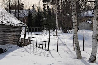
As you see we still have a lot of snow on the ground (and on my trailer...) although we had some very mild and rainy weather i February that cut off at least one foot of snow thicknesswise. But from the beginning of March weather turned very cold and still is, we have temperatures down to -15 ... -20 C every morning so far and it will continue for at least one week still. I cannot remember such a cold month of March since 1966.
Blame it on the sun... The sun should be at its peak of sunspot activity in solar cycle 24 now but this "peak" is very low, in fact as low as in the end of the "Dalton Minimum" in 1830 so I think we will have some cold winters and lousy summers to look forward to. I hope I'm wrong but the temperature statistics from the years after the Dalton Minimum may repeat themselves.
Anyhow, the sun let off a flare eruption accompanied with a massive Coronal Mass Ejection last Thursday and when that wave of energised particles arrived here on Sunday we got to see the most spectacular Northern Lights (Aurora Borealis) in many years. I grabbed my Nikon D90 and managed to get some nice pictures.
I have now been officially retired since the beginning of the year and I have been loafing around the house, winding down from my duties as a designer of very large network power transformers for the backbone grids of many countries and generator step-up transformers for many power generating companies all around the globe.
But, as an old radio amateur friend of mine got me interested in a special kind of end-fed antennas I flipped into transformer design mode again though the frequency is now megaHerzes insted of 50 or 60 Herz, the power is 100 - 200 Watts instead of several hundreds of millions of Watts (or MVA:s) and the weight is now around 100 g. instead of hundreds of tons.
The problem with end-fed antennas is that the feedpoint impedance (Z) is very high, 1500 - 3000 ohms and you have to in some vay transform that to suit the transmitter output that usually is built to operate at a source impedance (Z) of 50 ohm. If an end-fed antenna is cut to work on a specific frequency like 3.5 Mhz, it will also perform OK on harmonic frequencies like 7 MHz, 14 MHz etc.
The usual feed system is often a parallel resonance circuit (coil-capacitor) tuned to the antenna frequency and attached to the end of the antenna and the 50 ohm feedline is attached to a tap close to the bottom of the coil but then it will work OK at the resonance frequency only and you cannot use it on the harmonic frequencies.
Here we need a broadband matcing transformer instead. It is quite easy to build broadband RF- transformers for relatively low transformation ratios like 1:2 (Z-ratio 1:4) and 1:3 (Z-ratio 1:9) but here we need something with a Z- ratio in excess of 1:30! A turn ratio 1:6 would give a Z- ratio of 1:36 and to build an as broadband as possible RF-transformer with such a ratio has kept me going now since i retired... :)
I have tried using different combinations and sizes of ferrite ring cores, different ways of interleaving (braiding) the conductors involved and the best bandwidthwise so far the version "C" in the picture below.
It can handle about 100W CW and matches 50:1800 ohms from 3.5 to 18.1 MHz.
Version "A" is technically an enlarged version of "C" and can handle approx 250W from 6 MHz to 18.1 MHz but much to my dissappointment 3.5 MHz left out of reach. Version "B" is also 100W and covers 7.0 to 18.1 MHz and has the outer shield of a RG58U cable as primary winding.
More to follow...
And the Easter-Bunny is skipping around in our backyard:


